⬆ Top


Here we will cover how to setup a project in MPLAB X IDE for a PIC microcontroller and a mini tour of the MPLAB X IDE interface. As well as the the setup of the configuration bits for basic functionality of the PIC microcontroller. This is the baseline we will be using for all future projects unless otherwise stated.
It is also possible to change/add functionality to MPLAB X IDE but this is out of scope for our current goal of setting up a base project.
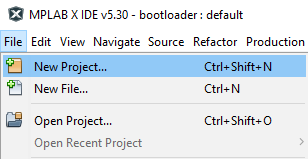
First thing we do is go to File then click New Project. An Other option is just to click the New Project Button.
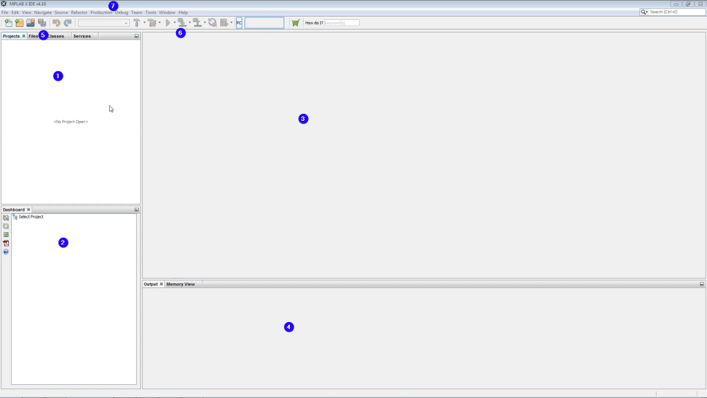
You will have this screen afterwards.
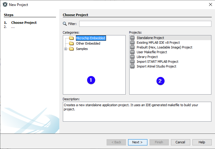
For the project we will be selecting Microchip Embedded with Standalone Project. Standalone Project is a clean project with no files added for us or any configuration.
Click next after selecting the project type.
The next screen will be the Device Select screen.
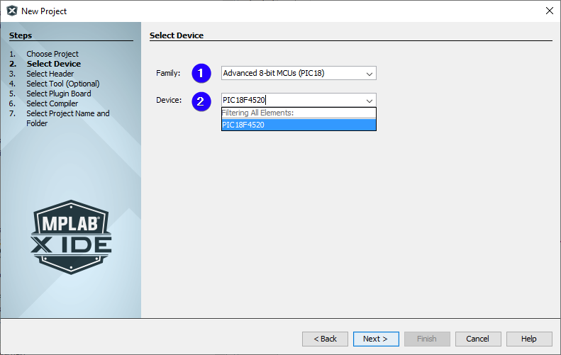
In most cases you will only need enter the part number of the microcontroller you wish to program. In this case the microcontroller will be a PIC18F4520 from the Advanced 8-bit MCUs (PIC18) family.
Something that is worth noting is that you can also program AVR MCUs in MPLAB X IDE.
Click next after selecting your microcontroller.
The next screen will be the Tool Select screen. Also known as the programmer select.
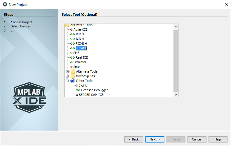
Here is where we select witch tool we are going to be using to program the PIC microcontroller with. In this case we are selecting a PICkit3.
After selecting your tool click next.
The next screen will be the compiler selection screen.
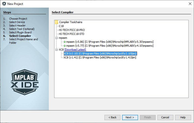
The compiler we will be using is the XC8 compiler that we downloaded in the software install tutorial.
You may have noticed that we have two compilers listed in the image above. If you have done a clean install then you should only have one option for the XC8 compiler. The reason we have two in the list is because we have update the compiler at some point and have not bothered to uninstall the older version.
mpasm are the assembler compiler that come with MPLAB X IDE.
After selecting the XC8 compiler click next.
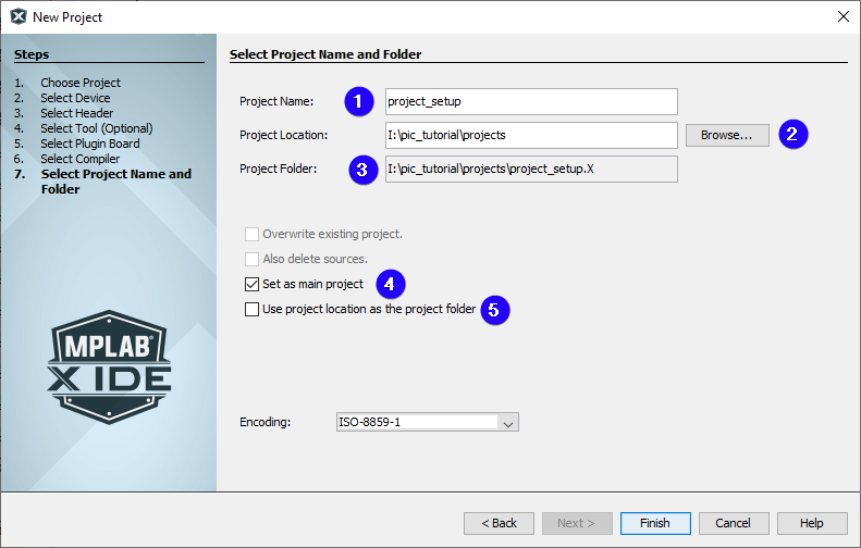
The next screen will be the Project Name and Folder.
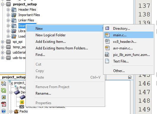
Next we need to add a main.c to the project. This is the start file of any program.
This is done by right-clicking Source Files > New > main.c…
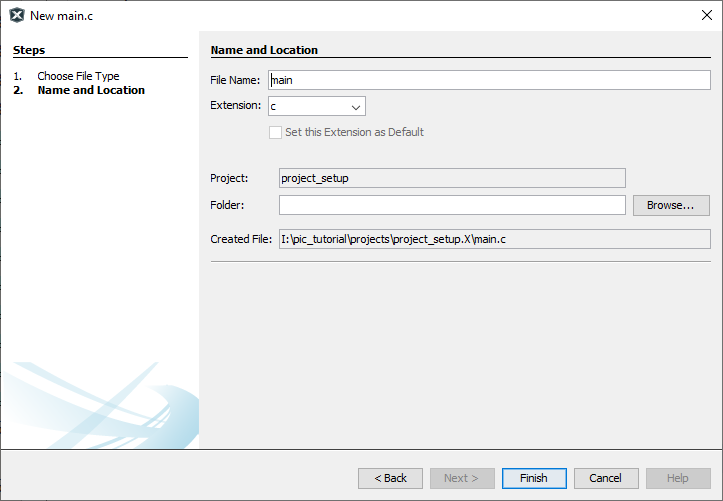
A screen will appear that you can configure the file. We will just be renaming the file to main and leaving the rest as default.
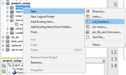
Next we need to add a conbits.h to the project. This will contain the configuration bits for the PIC microcontroller.
This is done by right-clicking Header Files > New > xc8_header.h…
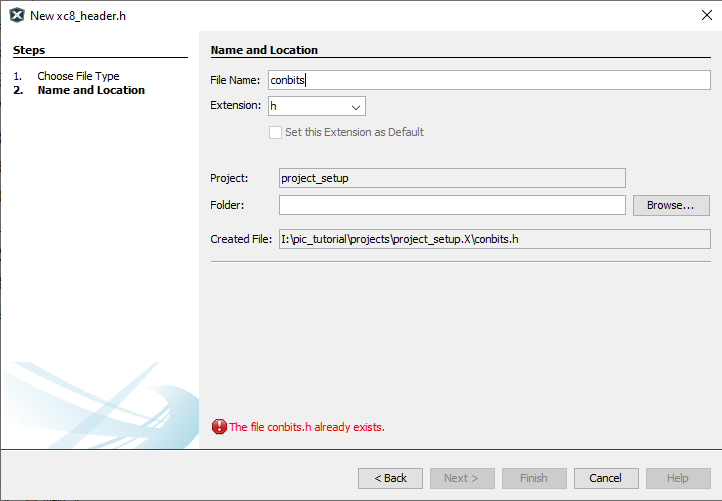
A screen will appear that you can configure the file. We will just be renaming the file to conbits and leaving the rest as default.
Now we need to include the conbits.h file into main.c.
#include <xc.h>
#include "conbits.h"

void main(void) {
    return;
}
Now the change the guard define from XC_HEADER_TEMPLATE_H too CONBITS_H and remove the comments to look like below in conbits.h.
#ifndef CONBITS_H
#define	CONBITS_H

#include <xc.h>

#endif
The project is now ready and setup.
The configuration bits control the basic operation of the PIC microcontroller. These settings are stored in flash and can only be modified with a flash write. The configuration bits are usually written to the flash when the PIC microcontroller is being programmed. The configuration bits are also sometimes referred to as fuses.
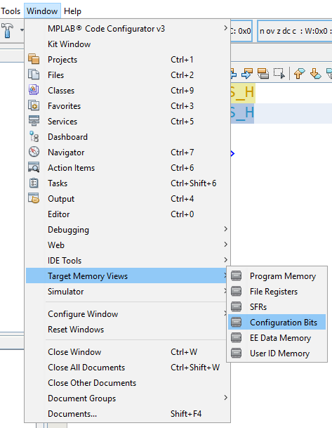
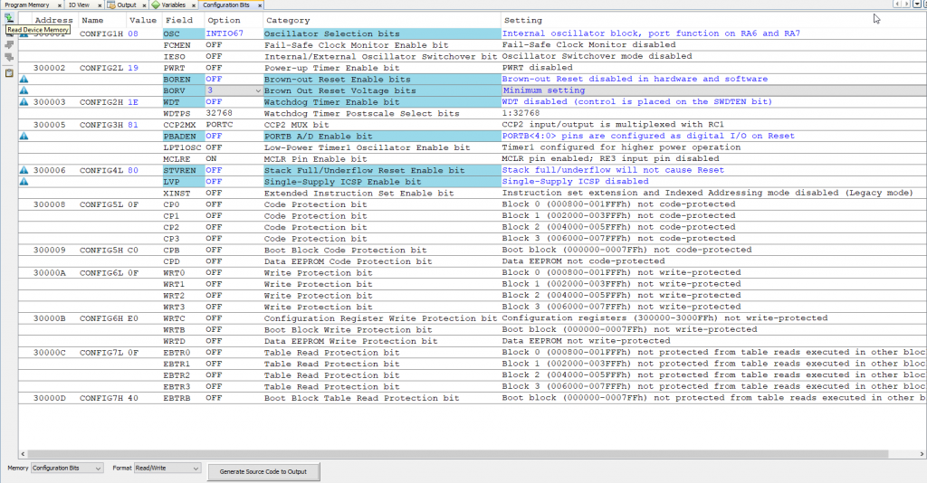
The configuration bits are accessed via Window > Target Memory Views > Configuration Bits.
The the following screen will appear. The blue highlights indicates changes.
This selects the clock source for the PIC microcontroller. The clock source is the most important configuration bit, without it nothing will run on the microcontroller. In this case we will be selection the internal oscillator with port function RA6 and RA7. If you want to use a external crystal as the oscillator you would typically select XT oscillator or HS oscillator. Please refer to section 2.0 Oscillator Configurations of the datasheet for more details.
This bit is uses to switch from one oscillator to another as a fail safe This is only uses when there is more than one oscillator available. This will be disabled.
This gives the PIC microcontroller the ability to switch between Internal and External Oscillators at runtime. This will be disabled.
This holds the PIC microcontroller in reset for approximate 65.6ms after power is applied. This will be disabled. Please refer to section 4.5 Device Reset Timers of the datasheet for more details.
Brown-out Reset will hold the PIC microcontroller in reset when the supply voltage drops below a set value. This will be disabled in hardware and software. Please refer to section 4.4 Brown-out Reset (BOR) datasheet for more details.
Selects the voltage level that the Brown-out Reset will trigger at. Since we have disabled the Brown-out Reset in hardware and software the value of these bits do not matter.
This is a independent timer from the PIC microcontroller. When this timer reaches it max value it will reset the PIC microcontroller. This will be disabled.
Watchdog Timer Postscale Select bits
Set the time it will take the Watchdog Timer to reset the PIC microcontroller. Since we disable the Watchdog Timer the value of these bits do not matter. Please refer to section 23.2 Watchdog Timer (WDT) datasheet for more details.
Set witch pin will be used for CCP2 input/output. In this case it will be multiplexed to RC1 pin.
Set the default config of PORTB bit 0 to 4 to be ether analog or digital pins on reset. We will be setting the default as digital pins.
Selects the power mode the Timer1 Oscillator will operate in. We will be selecting higher power mode. Please refer to section 12.3.2 Low-power Timer1 Option datasheet for more details.
This configures the MCLR pin as a digital input or as the reset pin. We higly recommend not using the MCLR pin as an input. We will set it as the reset pin.
This is mostly applicable to Assembler programming. This happens when “functions” returns invalid return address. We will be disabling this. More details available at Microchip Developer.
This is also known as the Low-Voltage ICSP Programming. It disable the need for the MCLR to be pulled high for programming. This has the trade off that RB5 is then dedicated to controlling the Programming mode and cannot be used as GPIO. We will be disabling this.
This adds extra Assembler instruction. However the XC8 compiler does not support extended instruction set so we will leave them disabled.
The rest of the configuration bits are code protection bits witch disables sections of ROM to be reprogrammed or read. Do not enable these bit unless you want do not want to reprogram your PIC microcontroller.
Now that we are done configuring the PIC microcontroller. Click Generate the Source Code to output.
Note: The configuration bits must be placed before any includes. Here we are placing the configuration bits in a header file. This negates the previous statement but conbits.h must still be placed in the same file as where the main function is called. The XC8 compiler is smart enough to move the configuration bits to the correct place at compile time when included from a header file.
Now copy the output of the configuration bits and paste it in conbits.h. Your conbits.h should now look like this.
#ifndef CONBITS_H
#define	CONBITS_H

#include <xc.h>

#pragma config OSC = INTIO67    // Oscillator Selection bits (Internal oscillator block, port function on RA6 and RA7)
#pragma config FCMEN = OFF      // Fail-Safe Clock Monitor Enable bit (Fail-Safe Clock Monitor disabled)
#pragma config IESO = OFF       // Internal/External Oscillator Switchover bit (Oscillator Switchover mode disabled)

// CONFIG2L
#pragma config PWRT = OFF       // Power-up Timer Enable bit (PWRT disabled)
#pragma config BOREN = OFF      // Brown-out Reset Enable bits (Brown-out Reset disabled in hardware and software)
#pragma config BORV = 3         // Brown Out Reset Voltage bits (Minimum setting)

// CONFIG2H
#pragma config WDT = OFF        // Watchdog Timer Enable bit (WDT disabled (control is placed on the SWDTEN bit))
#pragma config WDTPS = 32768    // Watchdog Timer Postscale Select bits (1:32768)

// CONFIG3H
#pragma config CCP2MX = PORTC   // CCP2 MUX bit (CCP2 input/output is multiplexed with RC1)
#pragma config PBADEN = OFF     // PORTB A/D Enable bit (PORTB<4:0> pins are configured as digital I/O on Reset)
#pragma config LPT1OSC = OFF    // Low-Power Timer1 Oscillator Enable bit (Timer1 configured for higher power operation)
#pragma config MCLRE = ON       // MCLR Pin Enable bit (MCLR pin enabled; RE3 input pin disabled)

// CONFIG4L
#pragma config STVREN = OFF     // Stack Full/Underflow Reset Enable bit (Stack full/underflow will not cause Reset)
#pragma config LVP = OFF        // Single-Supply ICSP Enable bit (Single-Supply ICSP disabled)
#pragma config XINST = OFF      // Extended Instruction Set Enable bit (Instruction set extension and Indexed Addressing mode disabled (Legacy mode))

// CONFIG5L
#pragma config CP0 = OFF        // Code Protection bit (Block 0 (000800-001FFFh) not code-protected)
#pragma config CP1 = OFF        // Code Protection bit (Block 1 (002000-003FFFh) not code-protected)
#pragma config CP2 = OFF        // Code Protection bit (Block 2 (004000-005FFFh) not code-protected)
#pragma config CP3 = OFF        // Code Protection bit (Block 3 (006000-007FFFh) not code-protected)

// CONFIG5H
#pragma config CPB = OFF        // Boot Block Code Protection bit (Boot block (000000-0007FFh) not code-protected)
#pragma config CPD = OFF        // Data EEPROM Code Protection bit (Data EEPROM not code-protected)

// CONFIG6L
#pragma config WRT0 = OFF       // Write Protection bit (Block 0 (000800-001FFFh) not write-protected)
#pragma config WRT1 = OFF       // Write Protection bit (Block 1 (002000-003FFFh) not write-protected)
#pragma config WRT2 = OFF       // Write Protection bit (Block 2 (004000-005FFFh) not write-protected)
#pragma config WRT3 = OFF       // Write Protection bit (Block 3 (006000-007FFFh) not write-protected)

// CONFIG6H
#pragma config WRTC = OFF       // Configuration Register Write Protection bit (Configuration registers (300000-3000FFh) not write-protected)
#pragma config WRTB = OFF       // Boot Block Write Protection bit (Boot block (000000-0007FFh) not write-protected)
#pragma config WRTD = OFF       // Data EEPROM Write Protection bit (Data EEPROM not write-protected)

// CONFIG7L
#pragma config EBTR0 = OFF      // Table Read Protection bit (Block 0 (000800-001FFFh) not protected from table reads executed in other blocks)
#pragma config EBTR1 = OFF      // Table Read Protection bit (Block 1 (002000-003FFFh) not protected from table reads executed in other blocks)
#pragma config EBTR2 = OFF      // Table Read Protection bit (Block 2 (004000-005FFFh) not protected from table reads executed in other blocks)
#pragma config EBTR3 = OFF      // Table Read Protection bit (Block 3 (006000-007FFFh) not protected from table reads executed in other blocks)

// CONFIG7H
#pragma config EBTRB = OFF      // Boot Block Table Read Protection bit (Boot block (000000-0007FFh) not protected from table reads executed in other blocks)

// #pragma config statements should precede project file includes.
// Use project enums instead of #define for ON and OFF.

#endif
Now we need to set the oscillator frequency so the XC8 compiler knows at what speed the PIC microcontroller will be running at. We do this by defining _XTAL_FREQ at the top of the conbits.h file in Hertz. The default internal oscillator frequency runs at 1MHz.
Your conbits.h should look like this now.
#ifndef CONBITS_H
#define	CONBITS_H

#include <xc.h>
#define _XTAL_FREQ 1000000

#pragma config OSC = INTIO67    // Oscillator Selection bits (Internal oscillator block, port function on RA6 and RA7)
#pragma config FCMEN = OFF      // Fail-Safe Clock Monitor Enable bit (Fail-Safe Clock Monitor disabled)
#pragma config IESO = OFF       // Internal/External Oscillator Switchover bit (Oscillator Switchover mode disabled)

// CONFIG2L
#pragma config PWRT = OFF       // Power-up Timer Enable bit (PWRT disabled)
#pragma config BOREN = OFF      // Brown-out Reset Enable bits (Brown-out Reset disabled in hardware and software)
#pragma config BORV = 3         // Brown Out Reset Voltage bits (Minimum setting)

// CONFIG2H
#pragma config WDT = OFF        // Watchdog Timer Enable bit (WDT disabled (control is placed on the SWDTEN bit))
#pragma config WDTPS = 32768    // Watchdog Timer Postscale Select bits (1:32768)

// CONFIG3H
#pragma config CCP2MX = PORTC   // CCP2 MUX bit (CCP2 input/output is multiplexed with RC1)
#pragma config PBADEN = OFF     // PORTB A/D Enable bit (PORTB<4:0> pins are configured as digital I/O on Reset)
#pragma config LPT1OSC = OFF    // Low-Power Timer1 Oscillator Enable bit (Timer1 configured for higher power operation)
#pragma config MCLRE = ON       // MCLR Pin Enable bit (MCLR pin enabled; RE3 input pin disabled)

// CONFIG4L
#pragma config STVREN = OFF     // Stack Full/Underflow Reset Enable bit (Stack full/underflow will not cause Reset)
#pragma config LVP = OFF        // Single-Supply ICSP Enable bit (Single-Supply ICSP disabled)
#pragma config XINST = OFF      // Extended Instruction Set Enable bit (Instruction set extension and Indexed Addressing mode disabled (Legacy mode))

// CONFIG5L
#pragma config CP0 = OFF        // Code Protection bit (Block 0 (000800-001FFFh) not code-protected)
#pragma config CP1 = OFF        // Code Protection bit (Block 1 (002000-003FFFh) not code-protected)
#pragma config CP2 = OFF        // Code Protection bit (Block 2 (004000-005FFFh) not code-protected)
#pragma config CP3 = OFF        // Code Protection bit (Block 3 (006000-007FFFh) not code-protected)

// CONFIG5H
#pragma config CPB = OFF        // Boot Block Code Protection bit (Boot block (000000-0007FFh) not code-protected)
#pragma config CPD = OFF        // Data EEPROM Code Protection bit (Data EEPROM not code-protected)

// CONFIG6L
#pragma config WRT0 = OFF       // Write Protection bit (Block 0 (000800-001FFFh) not write-protected)
#pragma config WRT1 = OFF       // Write Protection bit (Block 1 (002000-003FFFh) not write-protected)
#pragma config WRT2 = OFF       // Write Protection bit (Block 2 (004000-005FFFh) not write-protected)
#pragma config WRT3 = OFF       // Write Protection bit (Block 3 (006000-007FFFh) not write-protected)

// CONFIG6H
#pragma config WRTC = OFF       // Configuration Register Write Protection bit (Configuration registers (300000-3000FFh) not write-protected)
#pragma config WRTB = OFF       // Boot Block Write Protection bit (Boot block (000000-0007FFh) not write-protected)
#pragma config WRTD = OFF       // Data EEPROM Write Protection bit (Data EEPROM not write-protected)

// CONFIG7L
#pragma config EBTR0 = OFF      // Table Read Protection bit (Block 0 (000800-001FFFh) not protected from table reads executed in other blocks)
#pragma config EBTR1 = OFF      // Table Read Protection bit (Block 1 (002000-003FFFh) not protected from table reads executed in other blocks)
#pragma config EBTR2 = OFF      // Table Read Protection bit (Block 2 (004000-005FFFh) not protected from table reads executed in other blocks)
#pragma config EBTR3 = OFF      // Table Read Protection bit (Block 3 (006000-007FFFh) not protected from table reads executed in other blocks)

// CONFIG7H
#pragma config EBTRB = OFF      // Boot Block Table Read Protection bit (Boot block (000000-0007FFh) not protected from table reads executed in other blocks)

// #pragma config statements should precede project file includes.
// Use project enums instead of #define for ON and OFF.

#endif
We have now prepared the base project and can start doing the fun stuff.
Project Setup Example