⬆ Top


Here we will be covering the hardware required for PIC programming and how to connect the hardware to each part. These will be constant across all the tutorials.
Even though the Pickit can be used as a supply for the PIC we do not recommend using it as the supply as it can cause the USB controller to disconnect the Pickit form the BUS. This has the potential to brick the PIC microcontroller. Especially during uploading a program to the PIC microcontroller.
A 3A supply is not strictly necessary but is recommended. You can probably get away with using 500mA supply. A 500mA supply will however not be able to drive most DC or servos motors. A 3A supply will about cover any need you have.
A 5V supply is required for the PIC18F4520. The 2-5V supply range refers to the PIC18LF4520 variant of the microcontroller. Please refer to section 26.1 DC Characteristics of the datasheet.
The programmer we will be using with these tutorials is a Pickit3. This is used to upload firmware (the program) to the PIC microcontroller. We recommend getting a Pickit4 rather than a Pickit3 since new device support will be dropped as of 1 June 2019 for any new devices from Microchip. The only reason we are using a Pickit3 is because we have one on hand and it's compatible with the PIC18f4520 we will be using.
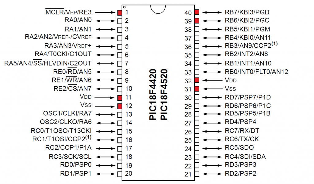
This pin is called memory clear. This pin is required to be pulled high for the PIC microcontroller to run / start executing code. When this pin is pulled low, it will reset the chip and the program/firmware will start from the beginning.
Pin 11 and 32 VDDThis is the positive supply (5V) of the microcontroller. You’ll note that there are 2 VDD pins. We recommend connecting both of the VDD pins always, as in some microcontrollers, some sections in the chip die may require a separate supply. This also allows for more current to be pushed though the chip as well.
Pin 12 and 31 VSSThis is the negative supply (0V) or ground (GND). We also recommend to connect both of these for the same reason state with VDD.
Pin 39 PGCThis is the program clock pin. This is used as the serial clock in the program/firmware into the PIC microcontroller. This is also referred to as the ICSP programming clock pin.
Pin 40 PCDThis is the program data pin. This receives the data from the from the Pickit to put in the program memory of the PIC microcontroller. This is also referred to as the ICSP programming data pin.
Pin 38 PGMThis is the Low-Voltage enable pin. This is only used when the supply voltage is not high enough to program the flash memory. This pin will not be used.
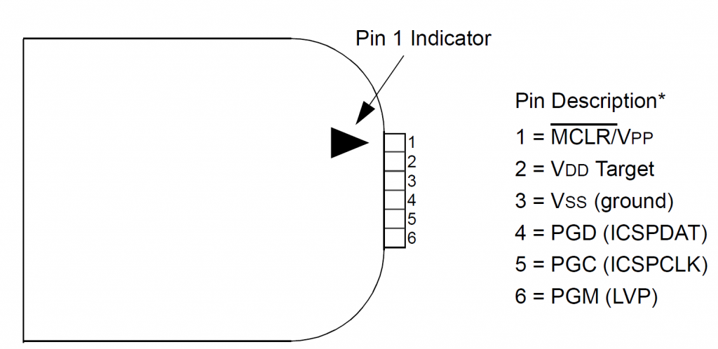
This pin is called memory clear, it controls the MCLR pin on the target microcontroller.
Pin 2 VDD TargetThis pin can do one of two things. It can either supply the target microcontroller with a set positive voltage or it can read if the target microcontroller is being powered. By default it is set to read.
Pin 3 VSSThis is the negative supply (0V) or ground (GND).
Pin 4 PGCThis is the program clock pin. This is used as the serial clock out to program firmware into the PIC microcontroller. This is also referred to as the ICSP programming clock pin.
Pin 5 PCDThis is the program data pin. This sends the data from the from the Pickit to put in the program memory of the PIC microcontroller. This is also referred to as the ICSP programming data pin.
Pin 6 PGMThis is the Low-Voltage enable pin. This is only used when the supply voltage is not high enough to program the flash memory. This pin will not be used.
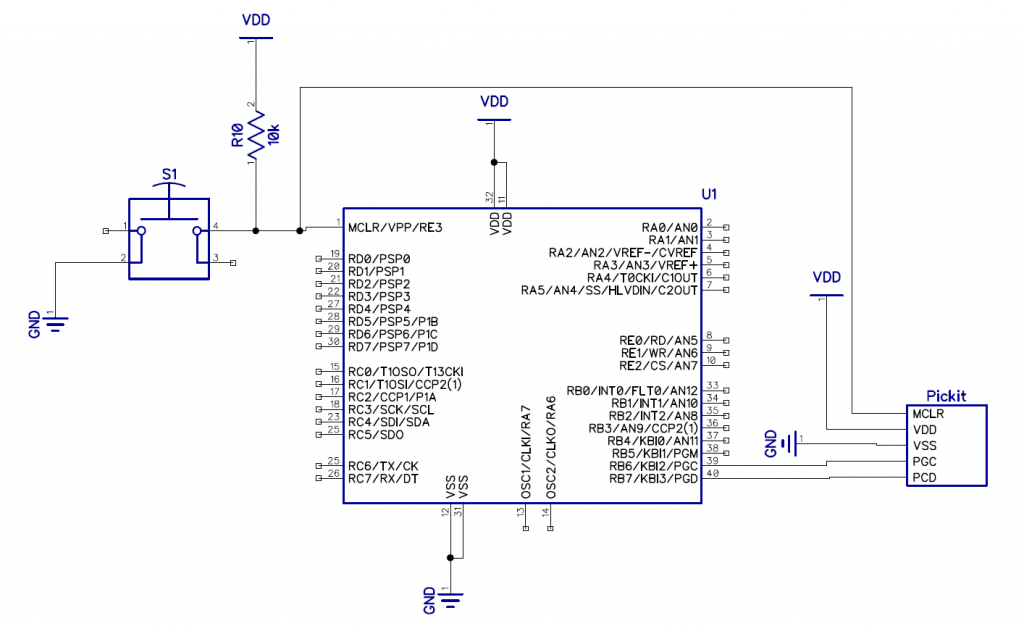
The connections from the Pickit to the PIC microcontroller are one to one for example PGC from the Pickit connects to the PGC on the PIC microcontroller. R10 is used to hold the PIC microcontroller in the running state by pulling it high. S1 is used as a manual reset. When the button is pushed it pulls the MCLR pin to Ground (GND) and resets the PIC microcontroller.