⬆ Top


This is how to use buttons as inputs and turn on a LED with a push button as the input on a PIC microcontroller. Creating a button push counter by adapting running LED code from the previous PIC microcontroller tutorial with debouncing. As well as a mode-swap from running LEDs to inverted running LEDs.
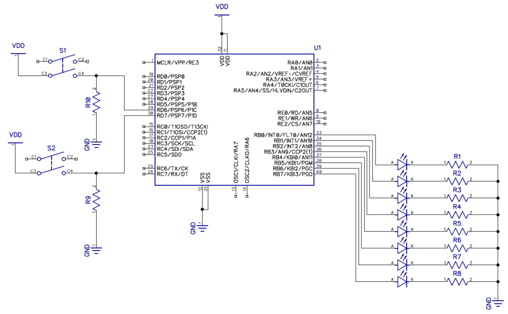
R9 and R10 are pull-down resistors. These resistors keep the input referenced to the ground supply line. This is referred to as a floating input when there is no reference for an input to the supply lines. If these resistors are not used then when reading an input (when the button is not pressed) it will result in random values being read.
S1 and S2 are the button inputs. With S1 being connected to RD6 and S2 connected RD7 on the PIC microcontroller PORTD. The other end of both buttons are connected to VDD (5V). When the button are pressed it will result in a 1 (on) on RD7 or RD6. If the button is not pressed it will result in a 0 (off) on RD7 or RD6.
NOTE: In general it is more common to have pull-up resistors on inputs. This will invert the logic of reading the inputs. With 1 being off and 0 being on. For explanation purposes it is much easier to understand a press as being 1 (on) and not being pressed as 0 (off). Some microcontroller also have internal pull-up and/or pull-down that can be set via registers.
Each pin on the PORTB is connected to a LED though a 330 Ω current limiting resistor (R1 to R8) to ground. This will be used as our display/feedback.
First thing is to set the TRISB register as all output so we can drive the LEDs. TRISB will be equal to 0. Also set the LATB register equal to 0 to turn off the LEDs. Then we have to set TRISD bit 7 and 6 as Input by setting only those two bits to 1. This can be done by using the TRISxbits structure. In this case it will be TRISDbits with members RD7 and RD6 set to 1.
NOTE: The REGISTERxbits structures can be used to edit individual sections of a register. This is useful when setting registers up for testing but the code itself will run slower. If only a single section of a register needs to be changed it will result in a speed gain. It also eliminates the need to faff with logic operations and bit masks to alter bits in a register. Witch can get complex fast.
#include <xc.h>
#include <pic18f4520.h>
#include "conbits.h"

void main(void) {
    TRISB=0; //0b00000000
    TRISDbits.RD7=1; //0b10000000
    TRISDbits.RD6=1; //0b11000000

    LATB=0; //0b00000000
    while(1){
    }
}
Now we need to read the state of the inputs. This is done by testing if the bit is 1 (High) on the PORTx register. In this case we will be testing if RD7 or RD6 is 1 (High). By using PORTDbits.RD7 and PORTDbits.RD6 with an if statement.
#include <xc.h>
#include <pic18f4520.h>
#include "conbits.h"

void main(void) {
    TRISB=0; //0b00000000
    TRISDbits.RD7=1; //0b10000000
    TRISDbits.RD6=1; //0b11000000

    LATB=0; //0b00000000

    while(1){

        if(PORTDbits.RD7==1){ //0b10000000
        }
        if(PORTDbits.RD6==1){ //0b01000000
        }
    }
}
Now that we can read the input we need to do something with it. We are going to turn on a LED when each button is pressed. For this case we are going to turn on the LED that is connected to RB0 when the button connected to RD7 is pressed and turn on the LED connected to RB1 when the button connected to RD6 is pressed.
The LEDs also needs a state when the button is not pressed otherwise you will press the button once and the LED will stay on with no way to turn it off unless you hard reset the PIC microcontroller. This can be done with a else statement after testing if the input on RD7 and RD6 is 1 (High). If the test fails then set the state of the LED to off.
#include <xc.h>
#include <pic18f4520.h>
#include "conbits.h"

void main(void) {
    TRISB=0; //0b00000000
    TRISDbits.RD7=1; //0b10000000
    TRISDbits.RD6=1; //0b11000000

    LATB=0; //0b00000000

    while(1){

        if(PORTDbits.RD7==1){ //0b10000000
            LATBbits.LB0=1;
        }else{
            LATBbits.LB0=0;
        }
        if(PORTDbits.RD6==1){ //0b01000000
            LATBbits.LB1=1;
        }else{
            LATBbits.LB1=0;
        }
    }
}
For counting button presses we import some of the code from the blinking LED tutorial. Specifically the code that handles the running LED section. This code is then placed inside the test for when RD7 is 1 (HIGH).
NOTE: The code is removed for RD7 and the else statements for both RD7 and RD6 as it is not needed.
Now we add a delay of about 250ms after the button press is detected on RD7. The value of delay is dependent on application and preference. If we do not add the delay after the button press is detected on the PIC microcontroller it will count a single button press as multiple button presses. This is referred to as a debouncing.
#include <xc.h>
#include <pic18f4520.h>
#include "conbits.h"

char run = 1;
char tracking = 0;

void main(void) {
    TRISB=0; //0b00000000
    TRISDbits.RD7=1; //0b10000000
    TRISDbits.RD6=1; //0b11000000

    LATB=0; //0b00000000

    while(1){

        if(PORTDbits.RD7==1){ //0b10000000
            __delay_ms(250);
            if(run >= 0x80){ //0b10000000
                run = 1;
            }else{
                run *= 2; //0b00001000
            }
            LATB=run;
        }
    }
}
For this segment we are going to create a program that will swap between 2 modes when the button is pressed. The two modes will be normal running LEDs and inverted running LEDs. We will use the following code as the base for it.
#include <xc.h>
#include <pic18f4520.h>
#include "conbits.h"

char run = 1;

void main(void) {
    TRISB=0; //0b00000000
    TRISDbits.RD7=1; //0b10000000
    TRISDbits.RD6=1; //0b11000000

    LATB=0; //0b00000000

    while(1){

        if(PORTDbits.RD7==1){ //0b10000000
            __delay_ms(250);
        }
    }
}
First what we do is add a variable (tracking) that can be use to track the current state that the program is in. This variable is then tested inside the test for when the button is pressed with a if and else if statement. Depending on the state of the tracking variable we need to set it to the opposite value.
#include <xc.h>
#include <pic18f4520.h>
#include "conbits.h"

char run = 1;
char tracking = 0;

void main(void) {
    TRISB=0; //0b00000000
    TRISDbits.RD7=1; //0b10000000
    TRISDbits.RD6=1; //0b11000000

    LATB=0; //0b00000000

    while(1){

        if(PORTDbits.RD7==1){ //0b10000000
            __delay_ms(250);
            if(tracking == 0){
                tracking = 1;
            }else if(tracking == 1){
                tracking = 0;
            }
        }
    }
}
After the testing of the tracking veritable is done. We add a while statement before exiting the if statement that detects if the button is still pushed. This loop will wait until the button is released. This is too lock the current state of the tracking veritable and freeze the code until the user releases the button. If this blocking loop is not used the PIC microcontroller will toggle between state while the button is pressed and held. This is another form of debouncing.
#include <xc.h>
#include <pic18f4520.h>
#include "conbits.h"

char run = 1;
char tracking = 0;

void main(void) {
    TRISB=0; //0b00000000
    TRISDbits.RD7=1; //0b10000000
    TRISDbits.RD6=1; //0b11000000

    LATB=0; //0b00000000

    while(1){

        if(PORTDbits.RD7==1){ //0b10000000
            __delay_ms(250);
            if(tracking == 0){
                tracking = 1;
            }else if(tracking == 1){
                tracking = 0;
            }
            while(PORTDbits.RD7==1);
        }
    }
}
Now we add the counter for the running LEDs code after after the button press detection.
hen we add a test to see in witch mode the PIC microcontroller is in. This is done by using an if statement with the tracking veritable. When the tracking veritable is equals to 0 the LEDs will not be inverted (normal running LEDs) and when it is equal to 1 the LEDs will be inverted. The inversion is done by using the ~ (not) operator.
A delay of 250ms is added at the end of the main loop to make the running LEDs visible to naked eye.
#include <xc.h>
#include <pic18f4520.h>
#include "conbits.h"

char run = 1;
char tracking = 0;

void main(void) {
    TRISB=0; //0b00000000
    TRISDbits.RD7=1; //0b10000000
    TRISDbits.RD6=1; //0b11000000

    LATB=0; //0b00000000

    while(1){

        if(PORTDbits.RD7==1){ //0b10000000
            __delay_ms(250);
            if(tracking == 0){
                tracking = 1;
            }else if(tracking == 1){
                tracking = 0;
            }
            while(PORTDbits.RD7==1);
        }

        if(run >= 0x80){ //0b10000000
            run = 1;
        }else{
            run *= 2; //0b00001000
        }
        if(tracking == 0){
            LATB=run;
        }
        if(tracking == 1){
            LATB=~run;
        }
        __delay_ms(250);
    }
}