⬆ Top


This is the hello world for any microcontroller. We will cover how to turn a LED on and off and create a running led sequence on a PIC microcontroller. Using the GPIO (general purpose input output) registers. These registers include the TRISx and LATx registers.
The first thing we need to add to the project is the header file for the PIC microcontroller you will be using. In this case it will be p18f4520.h. This file holds all the register definitions and the SFR (Special Function Registers) locations for the PIC microcontroller.
#include <xc.h>
#include <pic18f4520.h>
#include "conbits.h"

void main(void) {
    return;
}
Then we need to add a infinite loop in the main function and remove the return. The setup code (the code we only want to run once) will be running before the infinite loop. The infinite loop will be where the work will be done. This is usually a while(1) loop but for(;;) has become more prominent.
#include <xc.h>
#include <pic18f4520.h>
#include "conbits.h"

void main(void) {
    while(1){
    }
}
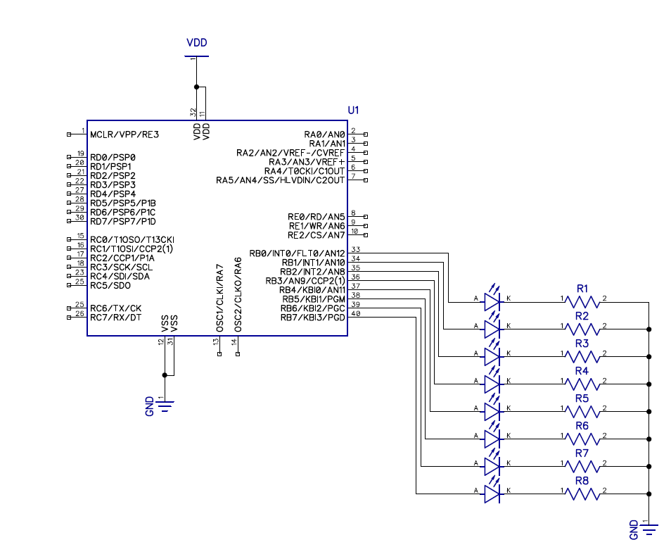
Then we need to set the pin, we are going to use to turn the led on as an output. This is done by using the TRISx register. TRIS stands for TRI-State. A GPIO pin can be in one of three states, output High (VDD) or Low (GND) or Input (High Impedance) hence the name TRI-State. This is somewhat misleading since the TRIS bits can only be in one of two stats, input or output, with 1 being input and 0 being output. The x will correspond to a letter assigned to each port on the PIC microcontroller. In this case it will be B so we will be using TRISB.
Each TRIS register consist of 8-bits. This is because we are using a 8-bit PIC microcontroller. This is also referred to as being 8-bit wide and will also be true for all registers. Each bit in the TRISB registers corresponds to a pin on the PIC microcontroller with bit 7 corresponding to RB7 and bit 0 corresponding to RB0. If a port does not have all the pins from 0-7 then you can assume those bits are unused.
Since we want all the pins on the B port to be outputs. We are going to set TRISB equal to zero.
#include <xc.h>
#include <pic18f4520.h>
#include "conbits.h"

void main(void) {
    TRISB=0; //0b00000000
    while(1){
    }
}
Now we need to to turn the LED on. This is done by using the LATx (Data Latch) register. If the PIC microcontroller does not have a LATx register you need to use PORTx. The main difference between the LATx and PORTx registers is that PORTx sets the actual voltage of the pins while LATx registers attempts to drive the pin to the High or Low value regardless of what the actual state is of the pins. It is not recommended to use PORTx registers to drive outputs.
A pin is set to High (5V) by writing a 1 and writing a 0 will set the pin Low (GND) for the corresponding bits on the LATx registers.
For this example we are going to set RB0 High. Turn on a led.
#include <xc.h>
#include <pic18f4520.h>
#include "conbits.h"

void main(void) {
    TRISB=0; //0b00000000
    LATB=1; //0b00000001
    while(1){
    }
}
To blink a LED we need to toggle the RB0 pin on and off. This is done by transitioning the LATB bit 0 from a 1 to a 0 repeatedly.
The rate at witch the LED will blink is determined by using a delay. The function used for this is __delay_ms(). The ms tag indicates that the time units are in milliseconds. The delay function is dependent on the _XTAL_FREQ define discussed in the project setup.
For this example we will be blinking the LED at 250ms intervals (250ms on and 250ms off).
#include <xc.h>
#include <pic18f4520.h>
#include "conbits.h"

void main(void) {
    TRISB=0; //0b00000000
    LATB=1; //0b00000001
    while(1){
        LATB=0; //0b00000000
        __delay_ms(250);
        LATB=1; //0b00000001
        __delay_ms(250);
    }
}
To create a running LED sequence we need to set only a single bit on and clearing the rest in the LATB register. This is done by counting in a binary sequence of 1, 2, 4, 8, 16, 32, 64, 128. The sequence will look as follows.
0b00000001 //1
0b00000010 //2
0b00000100 //4
0b00001000 //8
0b00010000 //16
0b00100000 //32
0b01000000 //64
0b10000000 //128
The binary sequence works in multiples of 2.
This value needs to be transferred from a variable to the LATB register. This variable also needs to be initialized as 1.
After the value reaches 128 (0x80) and is written to the LATB register, it needs to be reset back to 1. This is done by checking if the value is greater or equal to 128 and if it is, set the variable back to 1 otherwise multiply the variable by 2.
It is up too personal preference to clear the LATB register before writing the next sequence value to LATB.
#include <xc.h>
#include <pic18f4520.h>
#include "conbits.h"

char run =1;

void main(void) {
    TRISB=0;
    LATB=1;
    while(1){
        LATB=0;
        __delay_ms(250);
        LATB=run;
        __delay_ms(250);
        if(run >= 0x80){
            run = 1;
        }else{
            run *= 2;
        }
    }
}